Electronic Ballasts - Reprinted with permission from Filmcrew Magazine
Electronic Ballasts
by Harry C. Box
How still this quiet cornfield is tonight!
By an intenser glow the evening falls,
Bringing, not darkness, but deeper light...
-John Mansfield
This issue launches our newest departmental column, Deeper Light, written by Harry C. Box. The column will cover a wide range of in-depth technical issues from the electrical standpoint. Harry, a gaffer and cameraman with 13 years experience, is also the author of Set Lighting Technician's Handbook (Focal Press, 1993). The 2nd edition is due out this fall.
Five years ago you didn't see electronic flicker free ballasts very often they were a specialty item. Today every manufacturer offers electronic ballasts. The designs continually improve and become more and more sophisticated. With electronic ballasts fast on their way to being as common on sets as magnetic ballasts, their ship anchor predecessors, gaffers, best boys and electricians need to become familiar with a new protocol. To help out, here are some basics on how square wave ballasts compare to magnetic electronically and a look at a new area of trouble shooting.
Square Wave Ballasts
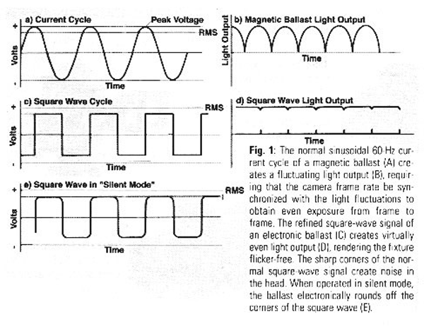
Square wave ballasts eliminate the flicker problem. They allow you to film at any frame rate, at changing frame rates and with a wild camera. A square wave ballast maintains a virtually constant output of light over the whole AC cycle by squaring off the curves of the AC sine wave (Figure 1 c). The change over period is so brief that the light is virtually continuous (Figure 1 d). Note that photo-sensitive "Cinecheck" meters do not give accurate readings when square wave ballasts are used.

Square wave ballasts completely process and regulate the input power, and as a result, they can tolerate fairly wide voltage and Hertz rate discrepancies. A typical 120V electronic ballast can take an input from 95V to 132V with out effecting the output signal and the fixture's color temperature. The refined signal also increases the light output by 6% to 8% and increases globe life as much as 20%.
Unfortunately, the square wave causes the globe and igniter to buzz. The head becomes a resonating chamber, amplifying the noise and projecting it out toward the set and the microphones. To make the ballasts quiet when recording dialogue, electronic ballasts are fitted with a switch to change between flicker free operation and silent operation. In the silent mode, a special circuit electronically rounds off the sharp corners of the square wave, which eliminates the noise (Figure1e).
In the silent mode, most. square-wave ballasts provide flicker-free light at frame rates up to about 34 frames per second (fps), and In flicker-free mode, up to 10,000 fps. Make sure that all ballasts are set to the same setting. Most electronic ballasts also have limited "dimming" capability. By controlling current, the ballast can dim the lamp 40 to 50% or about one stop of light. At 50% power, a globe's color temperature will be 75 to 200K higher (bluer) than normal. Some new ballast designs incorporate self-diagnostic messages on an LED display which identify an overheated power module, improper input voltage, a short in the output circuits, current on the ground wire, a misconnected cable-everything but a readout of the gaffer's pulse rate, handy for troubleshooting. If the ballast shuts off, be sure to check the display before rebooting the ballast.
Power Factor and Harmonic Current on the Neutral Wire
Until relatively recently many electronic ballasts were made without power factor correction circuits. Because of its heavily capacitive front end components, an electronic ballast puts current and voltage out of phase with one another. As a result, it typically has a power factor of 0.6 or less, meaning the ballast has to draw 40% more power than it uses. Associated with poor power factor are harmonic currents which build up on the neutral wire. Sixty-five to 80% of the current does not cancel out between phases, even when all hot legs are evenly loaded. This means that when operating a large number of electronic ballasts, the neutral wire will need to be doubled or even tripled to carry the additive current.
Power Gems ballasts (used by Strand, Leonetti, some Cinemills and LTM) and new Arri ballasts have power factor correction circuits. Lightmaker and Desisti (except the 18k and older ballasts by the others) do not. Power factor correction reduces heat, there-by increasing reliability; it uses power more efficiently and minimizes return current. It also weighs and costs a little more.
Ballast Electronics
A magnetic ballast is a very simple device. Input power is routed through the main breakers which protect the circuit in the event of a short. From there power is routed to the transformer. The transformer provides the start-up charge for the igniter circuit, then acts as a choke, regulating current to the lamp, once the light is burning. Power from the transformer is routed to the main contactors (which are controlled by a low-voltage control circuit) and to the igniter circuit wire.

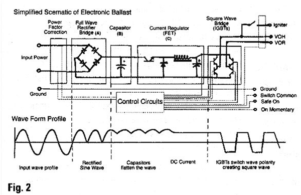
An electronic ballast on the other hand is quite a bit more complicated (Figure 2). Input current feeds through a full wave bridge rectifier, which inverts the negative half of the AC sine wave and makes it positive (the waveform looks like figure 1b at this point) then into a bank of capacitors which start to remove the 60 Hz rise and fall and flatten out the voltage-making it essentially DC. Current regulation is provided next, typically using a Field Effect Transistor (FET). At the final stage four specialized transistors (insulated gate bipolar transistors, or IGBTs) form a high-speed switching device which turns the flat current into an alternating square wave.
The frequency of the square wave is controlled by output control circuits attached to the ballasts little electronic cerebral cortex-the mother board. The square wave frequency is not referenced to the line Hertz rate. This means an electronic ballast will correct for a generator which is slightly off speed. Through out the ballast, control and safety circuits run back to the mother board. there are seven wires that run to the head. They are: two (thicker) power wires, VOH (voltage out hot) and VOR (voltage out return); a ground wire; the igniter's power line; and three 15-volt logic signal wires: switch common (15V from ballast); On momentary (remote On switch at the head); and safe on (which is wired to the micro-switch in the lens door and to the Off switch on the head.
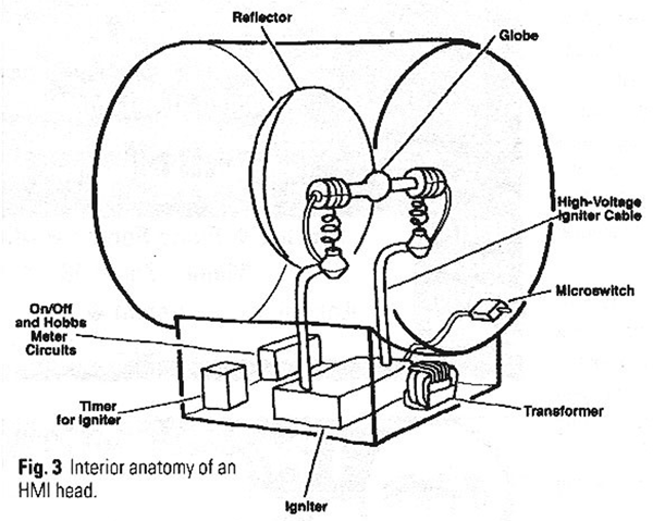
Both switches must be closed for the main contactors in a magnetic ballast to close (in the case of an electronic ballast, the power modules act as an electronic circuit breaker). In the head, VOR and VOH run directly to the terminals of the globe (Figure 3). The ground wire is connected to the lamp housing. The igniter's power line and VOR are connected to the primary step-up transformer of the igniter circuit. This transformer steps voltage up to about 5000 volts. From there, current runs through a spark gap to a secondary transformer which boosts voltage up to the starting voltage of the lamp-in the order of 17kV.
When the operator pushes the strike button two things happen: the contactors in the (magnetic) ballast are closed (in an electronic ballast the control board turns on the power control circuits-FETs and IGBTs-which applies voltage to VOR and VOH), and a 200V to 350V strike voltage is sent to the head on the igniter power line.

Taking it in extreme slow motion, the strike sequence happens as follows. The ignition voltage climbs from zero, increasing until the voltage potential is sufficient to bridge the spark gap. When a spark bridges the gap, a very high voltage start charge is delivered to the electrodes of the lamp from the secondary transformer. After 1 to 1.5 seconds a timer circuit removes igniter power from the circuit. Once the flow of electrons is initiated in the bulb, the ballast starts to hold back current. The lamp arc stabilizes and voltage rises to normal operating value.
The spark gap is set to deliver the proper strike voltage for the bulb. To some extent increasing the spark gap can improve hot restrike characteristics, because it increases strike voltage, however adjusting the spark gap involves special tools and an experienced technician; the parts are fragile and extremely small. Too narrow a gap will pro duce insufficient voltage to arc the bulb; with too wide a gap, the voltage will not bridge the spark gap. The lamp is turned off when the SAFE ON line is interrupted-either by the lens door micro-switch or by the OFF button on the head or ballast. This opens the main contactors in a magnetic ballast or shuts off the power control circuits in an electronic ballast.
Trouble-Shooting = Preventative Maintenance
Once an electronic ballast craps out, there is seldom anything you can do but replace it. Nothing inside an electronic ballast is user serviceable; you have to leave it to a qualified electronics technician. For this reason, preventative steps become all the more important. There are many things electricians can do to prevent a failure. The main one is to treat the equipment like an electronic device, not like a magnetic ballast. Magnetic ballasts are just about bullet proof, being made mostly of copper windings. They can take all kinds of abuse both physical and electrical without failing. Electronic ballasts are made of circuit boards, relays, capacitors and transistors; they are far more delicate. They must be handled gently and be thoroughly protected from moisture, condensation and precipitation.
The simplest and lightest ballasts are susceptible to blowing electronic parts. For example, repeated hot stabs can burn out the inrush resistor which protects the front-end rectifier bridge diodes and capacitors during start-up. The most common repairs revolve around damage to input rectifiers, vented (blown) capacitors, open inrush resistor or blown power module fuses-all caused by high inrush current. Always turn off the main On/Off switch or breaker after use, and make sure it is off before plugging in the power. Another common repair is damage to the output transistors (IGBTs and FETs) caused by a short or arc path in the head or head cable.
This is something that ballast designers have been improving; the newest ballasts include backend protection circuits-a sensor shuts it off if it senses a short. However with ballasts not so equipped, a shorted igniter circuit can burn out ballast after ballast. If a 12k makes a loud buzz and arcing sound when you attempt to strike, but does not take, check the igniter cables and lamp cables. If the lamp cables are hanging close to a metal part (such as the reflector), the start-up charge may arc (witnessed by blackened, fraying strands of cable and black pit marks). This shorts the ballast and deprives the bulb of the necessary start voltage. It also burns away the lamp cables over time.
Similarly avoid shorts in the head feeders by keeping the cables and connectors in good condition; check for bent or corroded pins or shorted or crossed wires. The head must be working properly, with a continuous ground, good igniter, and lamp cables well clear of metal parts to prevent arcing. In some cases the ballast will continue to work even though internal parts are damaged. The result is that other parts overheat and short out, and the repair bill and turn around time keep going up. The only way to avoid this is preventative maintenance-having a qualified electronics technician go through the ballast with an oscilloscope before it goes out. Warner Bros and CBS Studio Center are two studio shops I know of that have fully trained technicians who do this, and who can diagnose and repair electronic ballasts. Good Luck!